|
Page 3
It was at this point that I encountered a problem. I had built the frame according to plans and used the configuration for a V bottom boat. The main difference is that the cross supports are not straight but shaped in a "V" to accommodate the hull. As per plans, the springs are attached to two (one on each side) lengths of 2½" x 2½" x ¼ angle iron. These ride beneath the frame and create an undercarriage that can slide the axle back and forth to adjust the amount of weight on the tongue (60 to 65 LB suggested). But I encountered a problem when dry fitting in place. Because of the cross member drop down the angle iron hit the cross member and was prevented from mating flat to the bottom of the frame side rail. You can see the problem in the photo (view looking up from below the frame). The arrow actually on the cross member and pointing at the place the angle iron is hitting it.
Repositioning the cross members at this point was out of the question. The only solution that seemed to make sense was to "lower" the angle iron. The way I decided to do this was to weld ¼" spacers on the inside of the angle iron. I positioned five of these along the bottom and reasoned that the best location was under the five bolt holes I had punched* in the angle for the bolts to attach it to the frame. Also, two of the holes and spacers were stationed directly over the spring hanger brackets to eliminate any twisting to the angle that could result if it were unsupported.
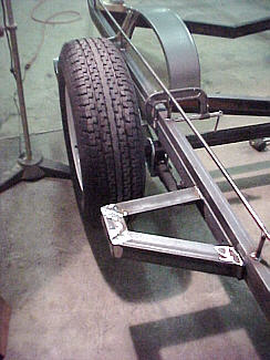
With this done I was ready to position the axle assembly under the
frame . I wanted the tires and wheels attached so I could determine where
the fenders need to placed. To establish the height clearance I measured
the space between the frame and the axle. It revealed that the total
travel of the spring was 3" before it hit the frame solid. I decided
to set the fender 4" above the tire. Once the height was set the
fenders were centered and then angle iron supports were welded to the side
of the frame. I had also decided I wanted a step both in front and behind
fenders. This would be handy when accessing the boat on the trailer
and also added extra beef to the fender mount. The photo shows the
front step welded to the angle iron. Be sure you cut the angle iron
undercarriage rails long enough to accommodate this if it is an option
you decide to incorporate.
* I was at my friends machine shop getting the 2½" angle I
needed and I was cutting it in a sheer that will handle up to 12" x 12"
x 1" thick angle !!!!! In the process I noticed that there
was a hole "punch" designed in to this machine and it was set up for 7/16"
holes. I slid the ¼" thick angle into it and punched the 10 holes
in less than a minute! It would have taken longer than that just to get
it setup in my drill press and than I would have to drill the holes.
Having the right tools sure can make a job easy!
|
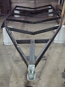 As
you can see I have now rolled the frame over and used plastic 6 gallon
buckets to raise it off the floor. I have positioned the coupler in preparation
to weld it in place. The
As
you can see I have now rolled the frame over and used plastic 6 gallon
buckets to raise it off the floor. I have positioned the coupler in preparation
to weld it in place. The 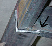 This
obviously was not going to work. If I had realized that this was
going to be a problem I would have been more careful in positioning the
cross members. I could have cut them so they were sitting a little
higher and most likely provided the needed clearance. But as the
say, hindsight is 20/20.
This
obviously was not going to work. If I had realized that this was
going to be a problem I would have been more careful in positioning the
cross members. I could have cut them so they were sitting a little
higher and most likely provided the needed clearance. But as the
say, hindsight is 20/20.
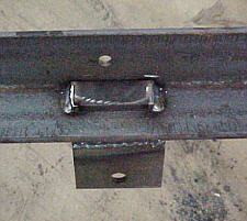 The
photo here shows one of the spacers in place with the bracket under it
and the bolt hole over. This solved the problem and the undercarriage
can now slide along the frame as per plans.
The
photo here shows one of the spacers in place with the bracket under it
and the bolt hole over. This solved the problem and the undercarriage
can now slide along the frame as per plans.