|
PAGE 13
I dug around the shop and came up with some scrap 1/8" plywood left over from one of my airplane projects (actually it is metric - 3 mm). This stuff is really neat in the fact that although it is only 1/8" thick it is 5 ply! I used poster board to make templates of the shape I wanted and then cut two pieces of the 1/8" ply. These were laminated together in place to form corner of the visor. A duplicate was made for the other side and a similar arrangement was used in the center. In-between these is just the normal 1/4" plywood. I used a couple of "stitches" to hold it in place until it is fiberglassed to the top. It worked out fairly well and gave me the look I wanted..
Because of this I wanted the windshields to tilt open a couple of inches a the bottom. I checked on some custom made commerical units that looked nice but they were out of my price range. So I constructed two new frames that matched the inside profile of the main windshield frame. I will rabbet the 1/4 laminated glass into the frames (glass ordered but not here yet). They are hinged at the top using 1" continuous aluminum hinge. I then needed something to control the amount of opening and support them firmly in place. I looked through several marine catalogs for the appropriate hardware and could find nothing I thought would work well for my installation. And what I did find were a little expensive at $25 to $40 each. I really wanted to place one at each lower corner of the windshield so I would have to buy four.
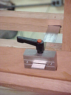
I think the picture will better explain how it works but basically
it uses a bolt (stud on a handle from Grizzly
Industrial) to jam against the sliding bar. The reason for the
two size slots were to accommodate an extra piece of 1/8" aluminum
to protect the sliding bar from damage from the stud. Without it
he bar would be quickly chewed up by the steel stud. The large slot
accommodates both the sliding bar and the jam shim while the smaller slot
allows only the bar to slide out while holding the shim in place.
This is screwed to the aft side of the windshield frame and allows for
quick and easy adjustment. A stop will be added to the end of the
sliding bar to prevent it from opening too far.
******************
|
 I
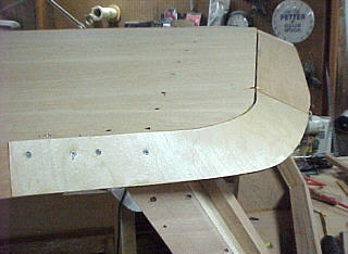
now had the hardtop in place but really didn't care for the look.
It just needed something to dress it up. I decided to add a side
"drip rail" and what I call a "visor" over the windshields. The drip
rails were just 1/4" plywood scraps set at a 20 degree angle - no problem.
But I wanted them to bend around the front corner of the cabin and flatten
out forming the visor. There was no way normal 1/4" plywood would
make this bend. I thought about using fiberglass laminations but
I am not very skilled working with it.
I
now had the hardtop in place but really didn't care for the look.
It just needed something to dress it up. I decided to add a side
"drip rail" and what I call a "visor" over the windshields. The drip
rails were just 1/4" plywood scraps set at a 20 degree angle - no problem.
But I wanted them to bend around the front corner of the cabin and flatten
out forming the visor. There was no way normal 1/4" plywood would
make this bend. I thought about using fiberglass laminations but
I am not very skilled working with it.
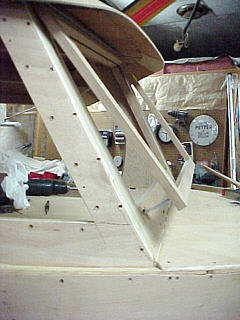 With
the visor glued in place I moved on to completing the windshields.
The plans called out to inset the glass into a rabbet cut around he windshield
frame. But as I mentioned before I wanted them to open. In
Illinois it gets hot and humid during the summers and I am afraid the enclosed
cabin may be uncomfortable with out some additional air flow. I also
plan for the side windows to open but am unsure of the amount of moving
air they will provide the pilot.
With
the visor glued in place I moved on to completing the windshields.
The plans called out to inset the glass into a rabbet cut around he windshield
frame. But as I mentioned before I wanted them to open. In
Illinois it gets hot and humid during the summers and I am afraid the enclosed
cabin may be uncomfortable with out some additional air flow. I also
plan for the side windows to open but am unsure of the amount of moving
air they will provide the pilot.
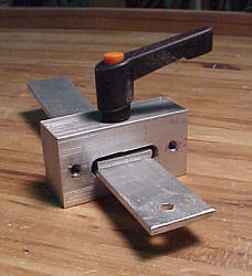 Once
again I decided I would have to make something myself. Fortunately
I have a small milling machine/lathe combo in the shop. After making
a few rough drawings I decided on a simple design I thought would work.
I dug around and found a piece of 1" square aluminum bar and cut off four
2 1/2 pieces. I cut one side down to 3/4" and then milled in a 3/8"
slot that was 5/8" deep. I then milled a 3/16 slot the rest of the
way through. A 1/4" hole was drilled and tapped in the side.
Once
again I decided I would have to make something myself. Fortunately
I have a small milling machine/lathe combo in the shop. After making
a few rough drawings I decided on a simple design I thought would work.
I dug around and found a piece of 1" square aluminum bar and cut off four
2 1/2 pieces. I cut one side down to 3/4" and then milled in a 3/8"
slot that was 5/8" deep. I then milled a 3/16 slot the rest of the
way through. A 1/4" hole was drilled and tapped in the side.