 With
the bottom now painted the hull was rolled upright and I am again able
to continue construction. I am really happy to be back measuring
and cutting wood. I know that paint/finishing is part of the project
but I enjoy working with wood. With
the bottom now painted the hull was rolled upright and I am again able
to continue construction. I am really happy to be back measuring
and cutting wood. I know that paint/finishing is part of the project
but I enjoy working with wood.
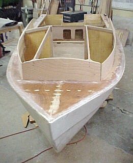
The first task was to add the forward bulkheads and then the cabin sides. These had to be custom cut as the plans because of my modifications. In fact at this point the plans are just serving as a visual guide to structure layout as none of the measurements or full size drawings will fit. I was prepared to use some OSB to make some templates when I noticed the templates I had made for the forward decks sitting in the corner. I set it on the deck and to my surprise the curve of the outside edge mated as the bottom edge if the cabin side wall. I couldn't believe it but I wasn't going to argue. I cut the sides and attached.
One of my goals in the modifications was to slightly lengthen the cabin side walls to provide better protection from the elements. My plan is to have a removable rear wall either of canvas or plywood. In looking at the Cabin Skiff photos it appear to me that the hardtop needs to be a little longer which also allows for the sides to br more vertical than per plans. The down side of this is it causes the top to be more than 48" (I ended up at 55") which means an additional piece of plywood is needed (+$).
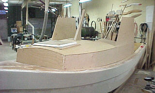
To make this work I cut a cleat that's outside profile matched the curved cabin side but inside profile was straight (see photo). I had also decided to make the window frame/side wall from plywood and it was attached to the straight side of the cleat. This set up the next assembly which was the windshield frame.
In addition the bottom must match the curve of the berth top and the top match the arch of the hardtop! It would have been a snap IF only I could use the patterns in the plans but they wouldn't fit. Matching the berth top wasn't to hard but the making the top of the windshield frames curve to match the hardtop had me stumped for a while - couldn't figure out how to do it! I had made the top of the frames plenty long knowing I would have to trim them. I went ahead and cut out the rear cabin beam (cross support between the cabin sides that will have the plywood top attached) and set it in place hoping that would help. It looked good but still couldn't figure out how to transfer the profile to the windshield frames tilted back at two angles. Standing there looking at it I suddenly had an idea. I pushed the rear beam up until it touched the back of the frames (still about 16 inches away rom the center). I them took a 300 watt quartz shop light on a stand and placed it near the transom. I turned it on and adjusted it so the bulb was the same height as the beam. It cast a shadow of the beam profile on the frame. I then just used a pencil and marked the edge of the shadow all the way across the frame. Crude but it worked. Photo 17 - rear views of cabin area. Photo 18 - Side view of cabin
|
 The
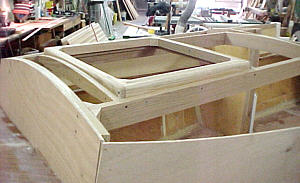
cleats were attached and the framing for the berth top. I had decided
I wanted a hatch and had purchased a Bowmar unit. The framing was
kind of like trying to put a square peg in a round hole. My goal
was to keep it as low to the cabin top as possible and not be to obtrusive.
I think it worked out fairly well. The 1/4 plywood top was then added
and things were beginning to take shape.
The
cleats were attached and the framing for the berth top. I had decided
I wanted a hatch and had purchased a Bowmar unit. The framing was
kind of like trying to put a square peg in a round hole. My goal
was to keep it as low to the cabin top as possible and not be to obtrusive.
I think it worked out fairly well. The 1/4 plywood top was then added
and things were beginning to take shape.
 Another
item on my list of changes had to do with the side windows and the windshields.
Because it get hot and humid in Illinois I was concerned about ventilation.
I had decided that I wanted the windows to slide open. I priced some
custom made units but quickly decided that they were more than I wanted
to pay. But no matter if I bought them or made them myself my modifications
had brought me to another problem. My cabin walls are now curved
and a sliding window arrangement needs to be mounted on a flat surface.
Another
item on my list of changes had to do with the side windows and the windshields.
Because it get hot and humid in Illinois I was concerned about ventilation.
I had decided that I wanted the windows to slide open. I priced some
custom made units but quickly decided that they were more than I wanted
to pay. But no matter if I bought them or made them myself my modifications
had brought me to another problem. My cabin walls are now curved
and a sliding window arrangement needs to be mounted on a flat surface.
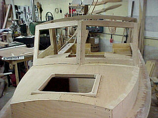 Again
because of my modifications I could not use the full size patterns. Plus
I wanted the windshield to be more glass and less wood than shown in the
plans. Making these from scratch proved to be the most challenging
part of the project to date. It really makes me appreciate the work
that Glenn-L has done in the design and layout of the CS. The frames
are made at compound angles leaning back in a "V" formation.
Again
because of my modifications I could not use the full size patterns. Plus
I wanted the windshield to be more glass and less wood than shown in the
plans. Making these from scratch proved to be the most challenging
part of the project to date. It really makes me appreciate the work
that Glenn-L has done in the design and layout of the CS. The frames
are made at compound angles leaning back in a "V" formation.