 The
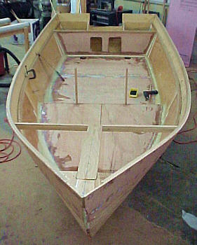
end of six weeks brings me to this point. The bulwarks are glued
in place and there is no turning back on my deck modification. Next
was to fabricate and dry fit the front deck support structure. Since
the positioning of the cabin front is now not dictated by the the corners
getting to close to the bulwarks I decided to move it forward about 6 inches.
I was somewhat concerned about the widening of the deck cross support caused
by mounting on the upper shear instead of the inner shear. Moving
it forward narrowed it to the original width or a little less plus made
the cabin a little longer. Also I have decided to add another cross
support in about 10" forward of the other (not shown). The reason
for this is I want the forward deck to be very solid. The Cabin Skiff
will be used on local rivers and boarding is often accomplished over the
bow - not many docks around! This extra support is probably not needed
but it was an easy addition so I will include it. The
end of six weeks brings me to this point. The bulwarks are glued
in place and there is no turning back on my deck modification. Next
was to fabricate and dry fit the front deck support structure. Since
the positioning of the cabin front is now not dictated by the the corners
getting to close to the bulwarks I decided to move it forward about 6 inches.
I was somewhat concerned about the widening of the deck cross support caused
by mounting on the upper shear instead of the inner shear. Moving
it forward narrowed it to the original width or a little less plus made
the cabin a little longer. Also I have decided to add another cross
support in about 10" forward of the other (not shown). The reason
for this is I want the forward deck to be very solid. The Cabin Skiff
will be used on local rivers and boarding is often accomplished over the
bow - not many docks around! This extra support is probably not needed
but it was an easy addition so I will include it.
Once the template was drawn I cut it out. After checking to make sure it fit on both sides of the hull I laid it on the plywood and traced around it to make the actual deck cutout. Again, it wouldn't fit on the plywood as per the plans as the increased width caused a problem. I was able to get both forward decks out of one sheet but nothing else. The aft decks were had to be cut from another sheet. Fortunately (or unfortunately) I have quite a selection of "scrap" created by my other modifications. I will state again I am amazed at how efficient the use of plywood is in the Glenn-L plans are - IF you are smart enough to stick with them!
In the picture you can see all the necessary fitting, ect. At the left top is the fuel line running from the bottom of the tank, up and through the top and splashwell wall. The lower left is a 1/4" thick aluminum plated recessed into the plywood and glassed on top. It is drilled and tapped for the fuel gauge sending unit. At the lower right is a 1 1/2" aluminum tube for the fuel fill hose and above it is the 5/8" fitting for the vent hose. In the center is an aluminum 2 1/2" threaded hole with that has a cap (not shown) that I added for and inspection access. The other tank is the same except there is no fuel gauge sending unit. The inside side of the tank top was covered with 4 layers of 8.9 oz. E fiberglass cloth and a wet layup of epoxy.
Photo #10 - Two views of the support structure of the forward deck. Photo #11 - Shot of fuel line tubing on tank interior Photo #12 - 3/4" hose fittings connecting two tanks. This view is looking down and aft through the area where the splashwell botom will be installed. The vertical structure in the center is the transom knee. The two aluminum tubs can be seen on each side where they pass through the tank side wall. Photo #13 - Fuel fill/vent as it will be mounted on the aft deck. The wedge block was used to improve angle between the tank and fill fitting. Block will be attached after decks are glassed. Photo #14 - Forward deck with plywood in
place for dry fit.
|
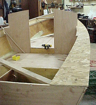 Next
was cutting the decks. Since I had moved them up to the upper shear
the patterns in the plans are not correct. Rather than take a chance
on wasting a large piece of expensive plywood because of a bad fit I bought
a 1/4" sheet of $8.00 OSB and used it to make a template. I laid
it on top of the hull and just traced around it for the outside profile.
I then took it off and placed in on the saw horses and drew out the inside
lines. I had decided I wanted a 6"+ deck width by the cabin for the
walk around. The actual deck was cut 8" which allowed 3/4" for the
cleat, 3/8" for the cabin side and another inch or so for the fillet. Note
the cleat is standing on edge rather than flat per plan. This was
necessary to bend it following the outside contour.
Next
was cutting the decks. Since I had moved them up to the upper shear
the patterns in the plans are not correct. Rather than take a chance
on wasting a large piece of expensive plywood because of a bad fit I bought
a 1/4" sheet of $8.00 OSB and used it to make a template. I laid
it on top of the hull and just traced around it for the outside profile.
I then took it off and placed in on the saw horses and drew out the inside
lines. I had decided I wanted a 6"+ deck width by the cabin for the
walk around. The actual deck was cut 8" which allowed 3/4" for the
cleat, 3/8" for the cabin side and another inch or so for the fillet. Note
the cleat is standing on edge rather than flat per plan. This was
necessary to bend it following the outside contour.
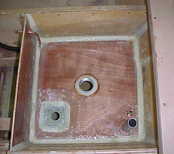 The
other accomplishment of the past two weeks is the completion of the fuel
tanks. The photo is looking down at the top of the tank while facing
forward. With the interior glass work done I then added the fuel pickup
line. I decided to use 3/8" ID soft copper tubing so I could bend to fit.
I drilled a hole in the splashwell side for the tubing to pass through.
The fuel hose will be attached there. The tubing was attached to the bottom
and sides with fiberglass tabs. I decided to include a fuel pickup
line on each side tank. This is not really needed because of the 3/4" line
that connect the bottom of the two tanks but again it was an easy addition.
The thought was that I believe there may be a gallon or so of unusable
fuel in the left tank because of the level of the 3/4" line. IF I am ever
so foolish to run out of gas I should be able to pull the fuel line off
the one side and move it to the other and use the all the fuel - kind of
an emergency reserve. (No, I have yet to run myself out of fuel but I have
sweat it out a few times!)
The
other accomplishment of the past two weeks is the completion of the fuel
tanks. The photo is looking down at the top of the tank while facing
forward. With the interior glass work done I then added the fuel pickup
line. I decided to use 3/8" ID soft copper tubing so I could bend to fit.
I drilled a hole in the splashwell side for the tubing to pass through.
The fuel hose will be attached there. The tubing was attached to the bottom
and sides with fiberglass tabs. I decided to include a fuel pickup
line on each side tank. This is not really needed because of the 3/4" line
that connect the bottom of the two tanks but again it was an easy addition.
The thought was that I believe there may be a gallon or so of unusable
fuel in the left tank because of the level of the 3/4" line. IF I am ever
so foolish to run out of gas I should be able to pull the fuel line off
the one side and move it to the other and use the all the fuel - kind of
an emergency reserve. (No, I have yet to run myself out of fuel but I have
sweat it out a few times!)
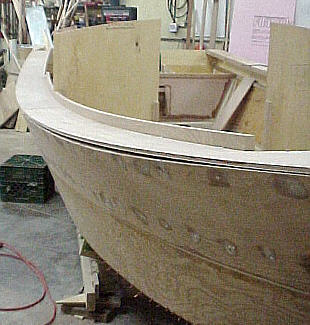 And
finally there is a picture of the decks dry fitted in place with the cabin
side cleat attached. The cabin bulkheads are temporarly screwed in place
and will be removed when the hull is rolled. I really like the graceful
look of the modification. Now the decks need to come off and be encapsulated
as well as the bulwark sides, cleats and forward deck support structure.
I am getting closer to turning the hull over to work on the outside.
I ordered the covering kit with the extra length of cloth needed to handle
the 18' length.
And
finally there is a picture of the decks dry fitted in place with the cabin
side cleat attached. The cabin bulkheads are temporarly screwed in place
and will be removed when the hull is rolled. I really like the graceful
look of the modification. Now the decks need to come off and be encapsulated
as well as the bulwark sides, cleats and forward deck support structure.
I am getting closer to turning the hull over to work on the outside.
I ordered the covering kit with the extra length of cloth needed to handle
the 18' length.