|
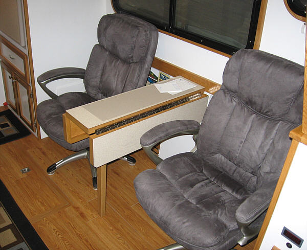
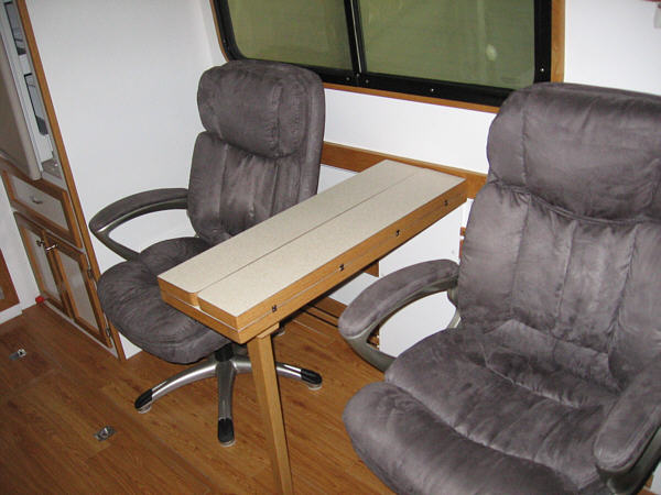
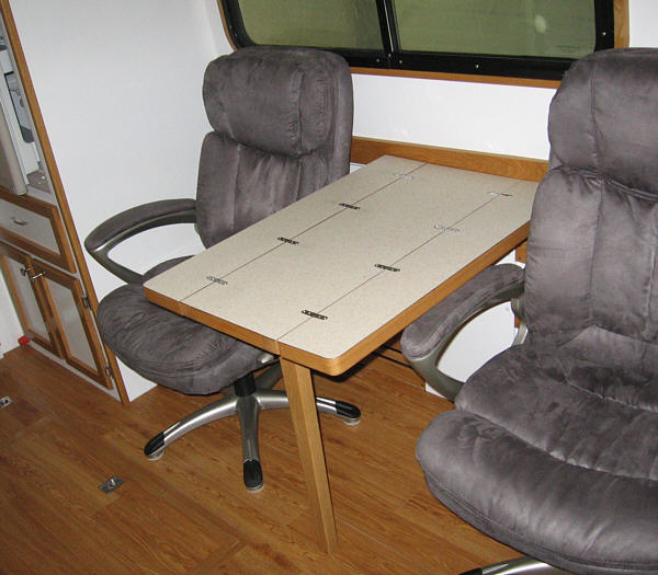
With Seaquinn's first season behind us, the spring of 2011 brought the opportunity for a few corrections and adjustments to several items. Over all I have been pleased with the boat but still there a few areas I felt needed to be addressed. The Table One of the first was the table in the saloon. During the build I struggled with the entire dining space, as it was extremely tight trying to incorporate the layout I wanted. The table needed to be kept as narrow as possible but still be usable for eating and such. I also wanted the chairs to have room to rotate 90 degrees and allow comfortable viewing of the LCD TV that would be situated on the countertop when in use. To accommodate both positions designed the table top with two folding wings that would drop down and allow more space when sitting 90 degrees to the top. This sort of worked but when rotating the chairs the arms would hit the folded wing. To change the wing position we had to get up out of the chair and slide it against the bulkhead, fold or unfold and move the chair back. Way too much hassle! I decided it would make more sense to remake the top and have the wings fold up onto the center section. Although I had to make the center section a little wider it works better because now the chair's arms can swing under the table with no problem. The result is we can flip the wing up or down at will without moving anything. Although it works much better, when opened the flush hinges to detract from the overall appearance (which my wife was quick to point out) but to me this is a classic case of form following function - and that works for me.
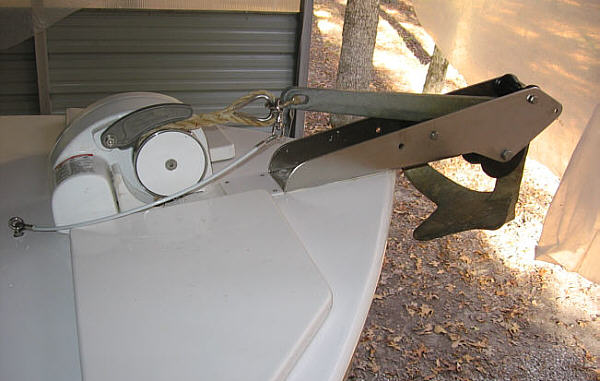
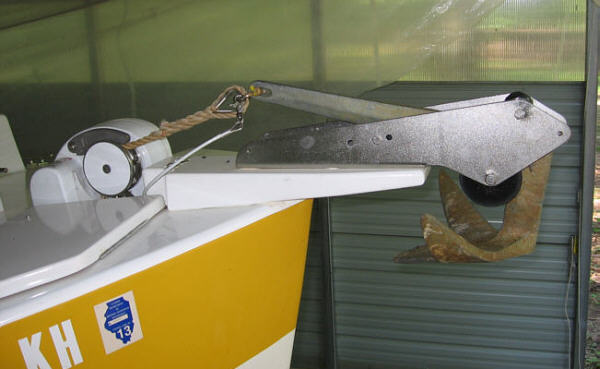
The Anchor Roller Another correction involved the anchor roller. To me one of the benefits of a windlass is to allow launching and retrieving the anchor without need to go forward every time. If the weather is mild and anchoring is temporary - like going for a quick swim - I am comfortable with just lowering the hook and not cleating off the rode. I had purchased a roller that was designed to allow a self-launch of my claw type 22 lb. anchor. The problem was it would not self-launch as intended. I decided the problem was the upsweep of the bow placing the anchor too close to the level position. The rollers were placed to create a downward slide but my installation was working against it. Also I had noticed that from time to time on retrieval the anchor would swing on the rode and contact the bow leaving a small mark.
The fix was to fabricate a tapered anchor pulpit that would recover the bow upsweep and move the front roller forward enough to prevent contact. I decided a six inch addition reach would alleviate the clearance problem and allow me to the needed taper. I used white oak to build the new pulpit and coated it with epoxy and painted. I then through bolted it and the anchor roller to the deck. That did the trick and now the anchor will self-launch and no longer pings the hull. In hind sight I should have made the pulpit longer and placed the windlass on top of it. This would have made the entire assembly much stronger but honestly it is very stout as is. BUT in the design process I again erred and did not make the cutout large enough to allow the one rode locker hatch to open completely. As a result next winter I will probably modify it. At that time I may make a new pulpit and place the windlass on top.
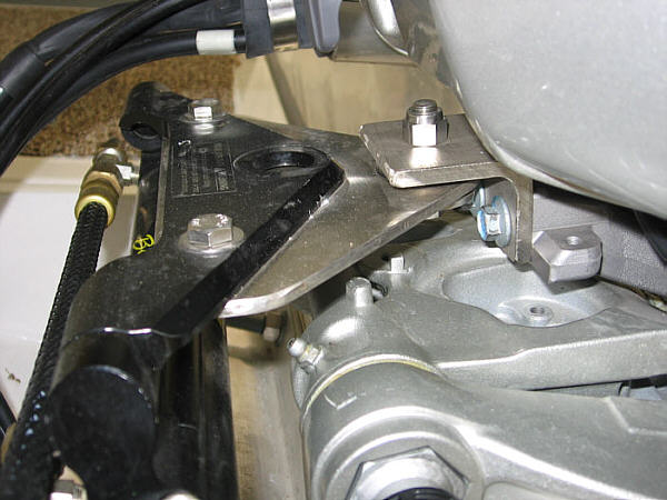
Steering Linkage An additional fix involved the steering linkage. One of the features that pushed me towards the Honda 60 Power Thrust was what they call "Easy Dock Steering". This allows the engine to pivot 50 degrees to both port and starboard compared to the industry standard of 35 degrees. This should allow a tighter turning radius and enhance close quarter maneuvering. I thought with a boat this size that would be a welcome asset. What I did not realize was although Honda included a special steering drag arm to make this work with a normal cable setup, there is currently no adapter available to implement this with BayStar or SeaStar hydraulic systems. I check with both Honda and Teleflex about a fix and both pointed their finger at the other. Lovely! As a result, my original install used the standard method of connection. It all worked well but only yielded the normal 35 degree deflection. Now I decided I was going to work out a fix to try to obtain the entire 50 degrees. This ended up being far more complicated that I had assumed. A lot of different forces are in action and clearance is tight. It made me realize the hydraulic steering system is a very elegant solution to a complex problem. My original thought was to try to incorporate the drag arm Honda provided but after several attempts I scrapped the idea. The only thing that seemed to have any potential was to extend the pivot point mounting plate of the hydraulic cylinder. I fabricated about four extensions out of thin mild steel to try to get the geometry correct. Finally after drilling, grinding and repositioning I found a combination that seemed to work. I still could not get the entire 50 degrees of swing but I am very close. Once the design was finalized I cut and machined the part from 3/16" stainless steel plate. I had never worked with that thick of stainless plate before and found it to be a learning experience itself. I didn't realize it was such tough stuff! I needed to drill a perfectly round 1" hole in it for the pivot bolt bushing. After two failed attempts I found myself searching the internet for information and with suggestions found I was finally able to get it accomplished. I also fabricated a new angled bracket for the pivot point attached to the engine. I could cut down the stock Honda bracked but if my design proved unworkable I would have to purchase a new onw to go back to the standard setup. Thought it wiser just to make a new one since I had a scrap of stainless angle that would work. The result of this modification is a noticeable decrease in the turning radius. This is very helpful when maneuvering around docks and slips. It was a time consuming project but in my opinion well worth the hours invested.
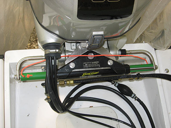
Here is more of a top view and may make it a little clearer. Moving the pivot point back was the key to gaining the extra swing.
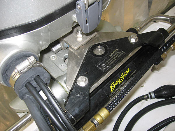
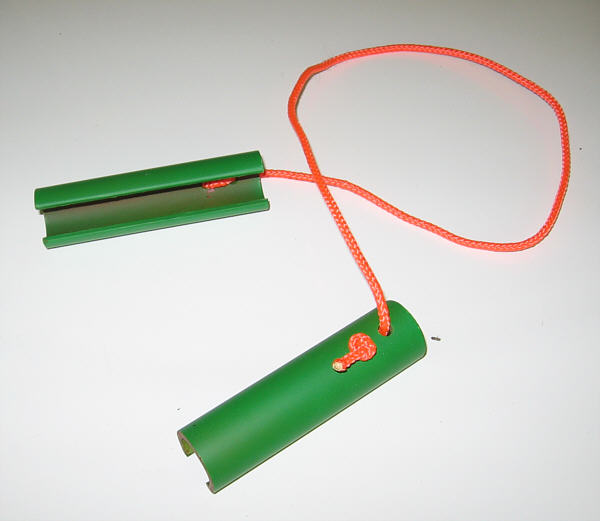
Steering Cylinder Stops A simpler modification to the steering system was making "stops" to hold the outboard centered. I have found if unrestrained the tilted motor has a tendency to rotate to one side or the other while being towed. This in turn tends to overstress the yoke of the support bar I have running up from the trailer to the lower unit. The fix was to cut two lengths of 3/4" PVC pipe long enough to fill the space on each side of the hydraulic cylinder. I then cut a section from the length of the pipe creating a slot just a little narrower than the cylinders 1/2" ram arm. The idea is I can center the outboard and then press these pieces of pipe over the shaft. The undersize slot prevents them from falling off. To ease removal I attached a piece of 3/16" nylon rope to each end. To remove I just pull on the cord and they pop off. The rope also aids in keeping them together making them harder to misplace. Finally, I painted the pipe a very bright green and used bright orange cording. This is to remind me they MUST be removed before launch or steering is impossible.
The stops are installed on the shaft. This also gives a wider view of the linkage extension.
The stops. The classic "simple but effective" made from 3/4" PVC electrical conduit .
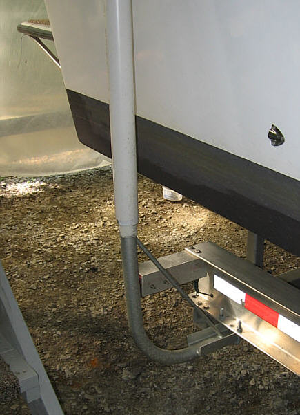
Trailer Guides The final item is something that has given me fits. I ordered with my trailer with guides to help align the boat when loading. I anticipated problems because of several factors.
What this all meant to me was the shallow V would not tend to self-center on the trailer like a deep V. And since the bow sits deep in the water the trailer would have to be in deep to accommodate it. As a result, the aft bunks would be very deep in the water and not helping hold the hull in alignment. Plus, if there was any crosswind it would easily push the aft end boat off the trailer. The idea of the guides were to hold the hull in place and then guide it down as the trailer was retrieved. Because the back of the trailer would be so deep in the water the guides would have to be long to do any good. And this is what causes the problem. Because they are so tall and the hull pushes against the top of the guide it has a LOT of leverage to bend the guide. My aluminum trailer came with 2" aluminum guide post covered with plastic pipe. The first time I had a cross wind at the ramp it bent the one side like a pretzel. I decided aluminum was going to do the trick so I bought 2" heavy wall (schedule 40) galvanized electrical conduit and bent them to shape (not an easy task but it helps to have friends with the right equipment!) STILL BENT THEM where they bolted to the trailer! Actually the problem was two fold. One - the pipes were mounted to the bottom of the trailer frame with U-bolts and even though I a total of four on each guide the force of the hull would still allow them to slip and then rotate forward pivoting within the u-bolts. Plus, if the side load was really strong it would bend the pipes outword right at the edge of the trailer frame. It just provided to much of a leverage arm. So I modified again. This time I welded to the guide a section of 3" steel channel that would sit flat against the frame bottom. They were secured with two 1/2"square type U-bolts. This stilled allows in and out adjustment but should prevent any rotation. Then I welded a 1/2" steel galvanized rod from the channel up to a higher point on the guide. This should add a good amount of strength to the guide and effectively reduce the length of the leverage arm. So far they have worked well but honestly they haven't been heavily stressed by higher winds. Time will tell.
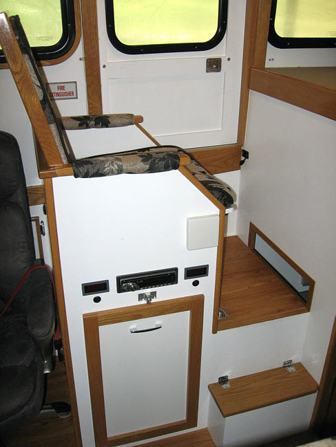
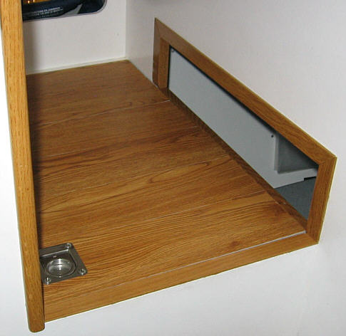
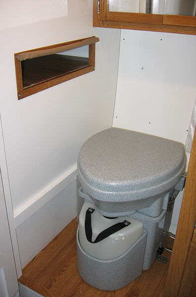
One final change was adding a little extra toe room for the passenger seat. As I mentioned earlier the layout on this side of the boat (table side) was very tight on space. With the help of a mock up I had determined what I thought was the minimum space required for comfortable foot room between the seat and the bulkhead. I then built accordingly. And although it proved to be acceptable for my wife it was not so for me. I could sit there just fine but found after a few minutes I was wishing for more space so my feet could move a little forward.
The solved the problem by cutting a rectangular hole at floor level through the bulkhead. This allows enough space I can move my feet ahead two of three inches and makes the seating position much more comfortable for me. My toes are more or less hanging over the edge and unsupported but this does not detract from the comfort. But the fix it is not without a negative side. The other side of the bulkhead is water closet where the head is sitting so this hole, although small, does add a "window" to the enclosure. Since the vast majority of time it is only my wife and I on board this is not a problem. But to handle the occasional guest I made a cloth roll down curtain that provides the desired privacy. I admit the fix is a little non-conventional but believe it will serve us well.
AND one other Lesson! In the process I learned another interesting lesson. In order to weld the galvanized steel the galvanizing needs to be removed. The easiest way I know to do this is to coat it with a little muriatic acid (hydrochloric acid). This is usually available at places that sell swimming pool or spa supplies. It very quickly eats the galvanizing off and allows clean welds. But be careful, this stuff is nasty - very nasty as I will find out.
I brushed the acid on the 2" pipe but for the rod I just poured a little in a plastic cup and set the rod into it. In a minute or two the process was complete and the parts were washed with clean water. (Again, be VERY careful). When I finished the rods rather than disposing of the remaining liquid, which was only about 3/8" in the bottom of the cup, I sat it up on the back side of one of my work benches thinking I might need a little again before the project was complete.
Well I didn't and I forgot about it. About a month later I was walking by the bench and I noticed tools hanging on pegboard behind it were a rusted mess. What the ______!, I thought. The more I looked the more rusted tools I saw - screwdrivers, chisels, knives, adjustable wrenches, hammers. Some were over 2 1/2 feet above the bench top.
I was totally baffled as to what had happened until I looked down and saw the open cup with a little of muriatic acid still in it. Just the fumes off the stuff was caustic enough to severely rust everything steel anywhere near it. Like I said - NASTY STUFF - use with caution and some common sense. Obviously, I had neither that day.
|