Now the hull was upright the next task was to add the support structure for the sole. The plans gave no indication as to how this should be accomplished. I wanted a solid floor but want to keep the size of the framing members to a minimal to maximize the area below for fuel and water tanks as well as storage. Naturally, the top of the frames would provide the main cross support but the question was how to tie it all together. This was complicated as the plans call-out for the sole plywood was only 1/2" thick and unless very well supported it would be spongy.
I decided to go with 1 1/4" x 2 1/2" members and form a gridwork to support the somewhat thin ply. I also determined the spacing between members should be no more than 12" and preferably 9" to 10". This meant there was going to be a LOT of joints and the next decision was what joint to use. A straight butt joint would be the easiest but also the weakest. Plus, all length cuts would have to be very exact. After a little research I decided on a modified butt as illustrated below.
The end of one member was cut at a 7 degree angle. In the receiving member I cut a slot or dado yielding the same 7 degree angle. To create these cuts I made a simple jig for my small cordless router which I could either clamp or screw to the receiving member. I could then machine these slots very accurately and quickly.
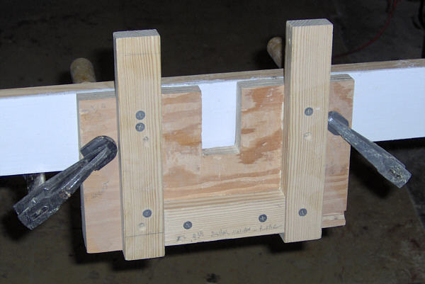
Here is a photo of the front of the jig. Set the top edge of the ply to the top of the beam. I was using my cordless router which has a 3" square base
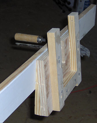
This side view shoes the 7 dregee angle set by block attached to the rear of the plywood. For non attached pieces I made another jig for the radial arm saw and using a dado blade could again cut these quickly. This joint has several advantages.
1. More glue surface than a straight butt.
2. With the jig it is easy to make.
3. As downward pressure is applied the joint becomes tighter as it is wedging itself in.
4. Since the dado only removes about a 1/4" of material at the top it weakens the female member very little. (Cut in drawing is exaggertated)
To secure the pieces I decided on putting my Kreg Pocket Hole jig to good use. I ordered some stainless steel pocket hole screws which were used in conjunction with glue to hold the joint. This made and extremely strong joint as well as easy and quick to cut. I did make one concession. I decided to buy a second compound miter saw I could setup in the boat. I have a nice 12" saw mounted on a 15' table in the shop and I didn't want to uproot it. But climbing in and out of the boat which stands more than 4 feet off the floor to make all these cuts (and recuts) was more than I wanted to attempt. I purchased a Porter Cable 10" unit with twin lasers and it has saved me hunderds of trips in and out of the boat.
Also, cutting the accurate length of the male member is quite easy. I would first cut the 7 degree angle on one end. Then flip it up side down placing the cut end in at the very top edge of one of the dados. I could then reach up from the bottom and using a sharp pencil, mark the other end at the back of the opposing dado. The drawing above better explains. Back to the miter saw I could use this line to cut the 7 degree angle on the other end. Usually it would snug in to place with no other trimming needed.
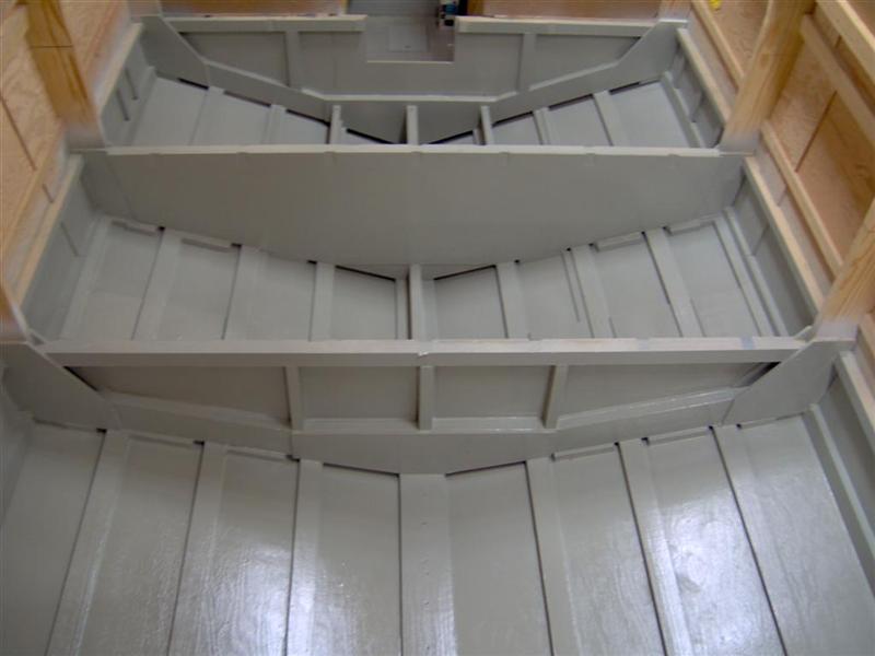
Decided it would be much easier to paint the bottom of the hull before the sole structure was added.
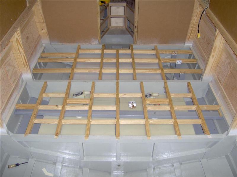
Before adding the structure the tanks were posistioned and mounted. This is looking forward with the berth bulkhead at the top of the photo. There are two 40 gallon water tanks in the upper bay and two 40 gallon gas tanks in the other. The bay with the fuel tanks is sealed from the rest of the hull interior. Bilge water and air can move beneath but the chamber for the gas tanks get air only from exterior vents.
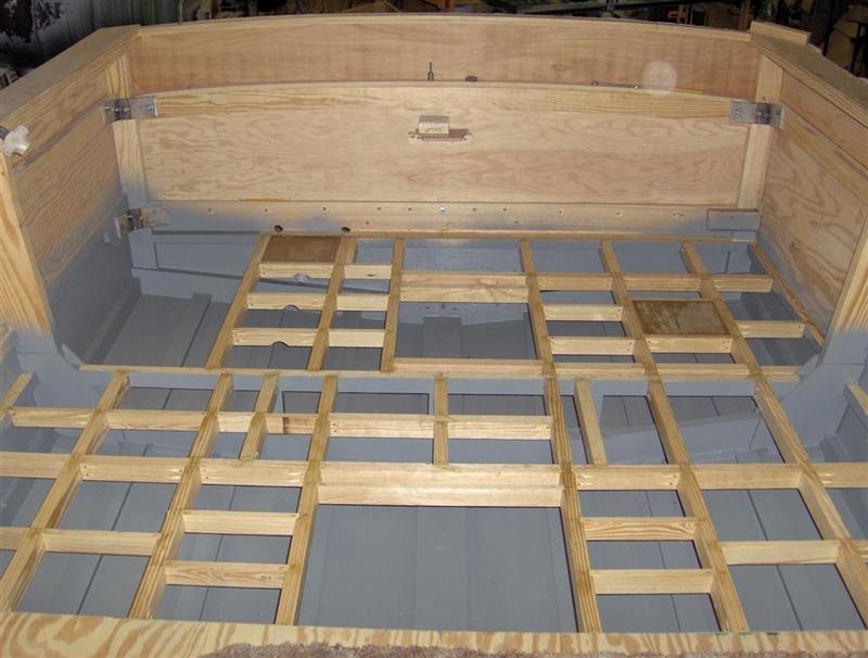
The aft structure with the transom at the top of the photo. Large openings are for hatches and storage boxes. In order to save space I fabricated the corner knees out of 3/8" thick stainless steel and bolted then through the hull and transom.
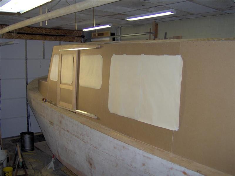
With the sole in place I next added the cabin walls. Although the hull was all marine douglas fir plywood for the cabin I elected to use MDO. Paper mock-ups for the windows were made to help decide on size. As you can tell I want a lot of glass. The cabin is going to be customized to my liking. I have lengthened it and added sliding forward doors which were not called out on the True Grit. Since I will be running through river locks I feel the doors are mandatory for handling lines.
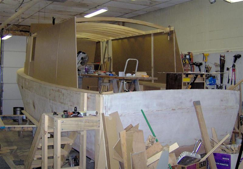
Adding the top beams. I used the same tapered butt joint as with the sole structure. Note that it takes six steps to get me over the hull side and then two back down to the sole. When building a boat this size you can forget the "Stair Master." I probably make this climb in and out at least ten times and hour.
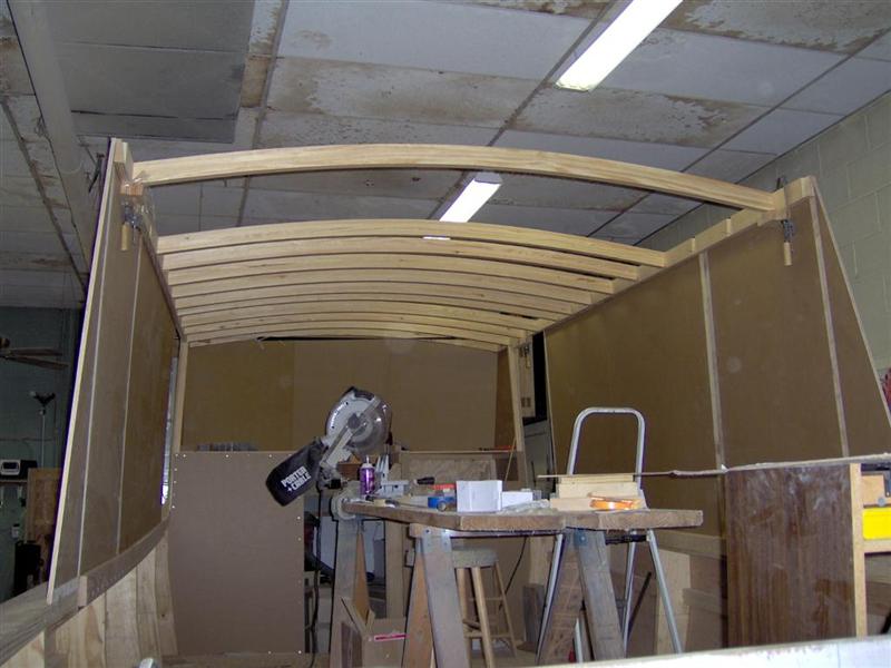
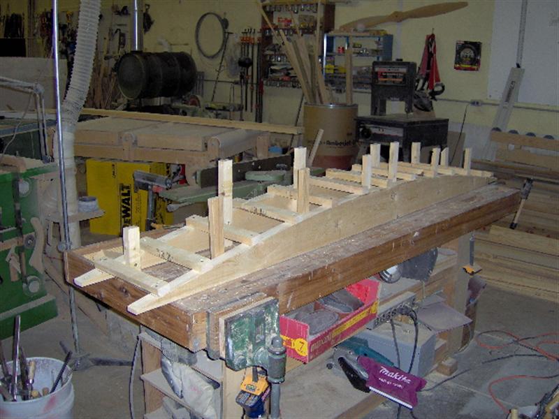
The beams were laminated from four layers over this building form. The vertical post were used to keep the lamination square. They were protected from the glue with wax paper.
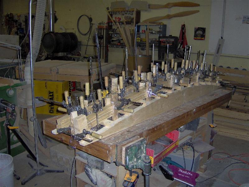
I could glue-up two at a time. Running them through the thickness planer cleaned the sides up nicely.
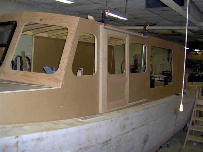
Rough openings for windows cut and windshield frames added. The windshield frames were in my opinion the most challenging layout project of the entire build.
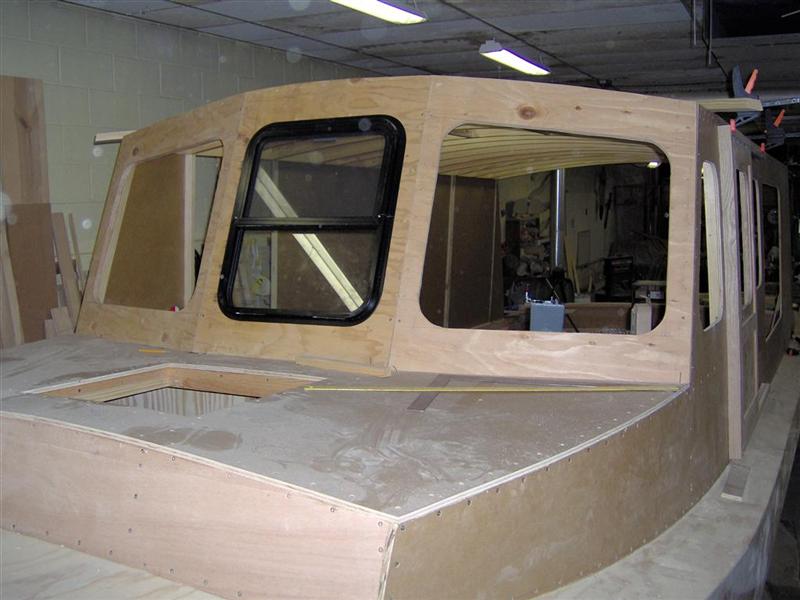
Windshield frames and berth trunk.
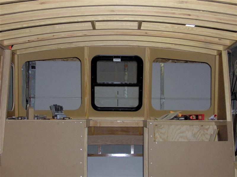
Interior view of windshield. Post between are wider than I would have liked but was the best I could do with the windows I plan to use.
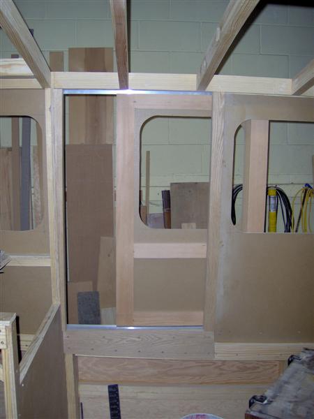
Interior view of the sliding door.