It
is important to
remember I am not trained as an engineer nor do I have any experience
designing something like this but I did spend a lot of time trying to
think my way through it. The problem with this is I had no way of
knowing for sure if it was going to be capable of handling the load.
The last
thing I wanted was a failure resulting in the O/B skidding down the
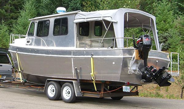
highway. This image came to mind because my thought is the
bracket would see the most
stress while being trailered. As the trailer hits bumps the full
weight of the O/B would pushing straight down trying to tear the top of
the bracket off the transom. I felt these hammering forces would
be much
greater than anything ever occurring on the water while pushing the
boat. As a result, the bracket is probably way over built - at
least for a 60 hp O/B weighing about 260 pounds. The box assembly is heavy, particularly
the mounting plate but more on this later.
The transom on my TG is one layer of 3/4" ply. On the inside I added a 2" x 4" beam running all the way across. It is glued flat to the transom and is just above the sole structure. This allows the sole to add support to the transom and eliminates the possibility of it having any fore or aft flexing. Then 2" x 2" cleats were bolted on the outside of the transom matching the inside profile of the front edge of the box. The box slipped over these and it was bolted to them from all sides. This holds it firmly in place.
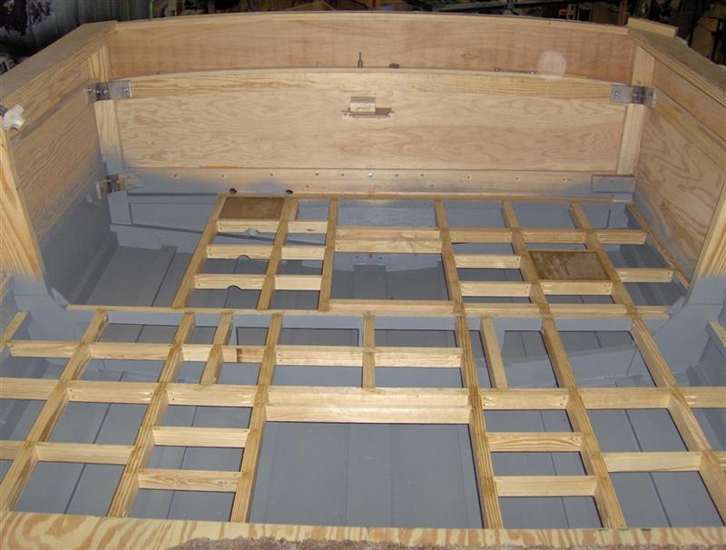
This
view is standing near the helm looking aft at the transom. To
save corner space 3/8" x 5" wide "L" brackets were fabricated
from stainless steel for the knees. The lower right bracket was
eliminated as the sole handled the load.
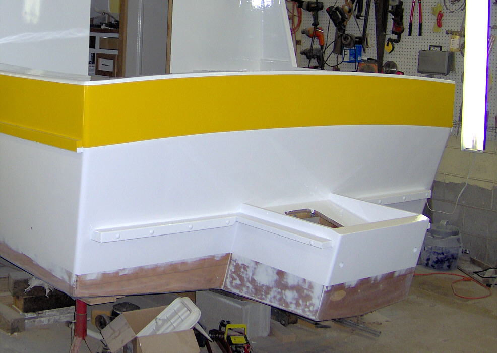
On the outside of the
transom I added horizontal cleats on each side of the mount box.
These are bolted through the transom and through the interior 2"
x 4". Another cleat was bolted along the top edge of the side
of the box. These serve as the mounting cleats for the swim
platforms which are bolted vertically through them. Here is a photo
showing the exterior cleats -
The sides of the box are 3/4" and if doing it again I think 5/8” or even 1/2" would have been plenty. The bottom and top are 1/2". The back where the O/B is mounted is the traditional 3 layers of 3/4" ply. If going with a 60 hp again I might well consider just two layers. The box's interior back corners are reinforced with 2" x 3" cleats. The 4" edge is glued and screwed to the 3/4" sides. The 2" edge of the cleat is attached to the box back (O/B mounting plate) with 3/8" bolts with the heads on the outside, counter sunk and epoxied over.
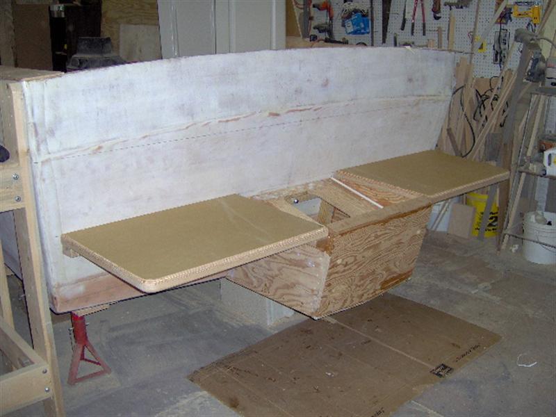
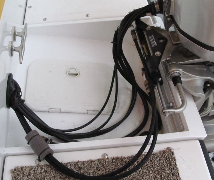
My whole idea was to form
a structure to spread support across the entire transom. The swim
platforms are not just for convenience - they are structural
members. Bolted to the box they form a wide flat beam across the full
width. When trailering the forces will be down at the rear of the
box. In order for it to come loose it must pull not only the box
away at the top but the platforms too. When under power the forward
pushing force is also spread across the entire transom by the
platforms. I'm certainly no expert but I think the design is solid
and will easily handle the load.
I did find though the outside corners of the platforms were a little springy when standing on them. To remedy this I simply added a diagonal support fabricated from 1” stainless steel tubing. It was flattened on the ends and screwed to the transom and bottom side of the platform.
BUT the problem I struggled with during the build was worrying about the weight. The combined weight of the box and platforms is about 100 lbs! Plus I am hanging a 260 lb O/B two feet "behind" the transom. I was very concerned about causing the hull to squat. I had seen photos of a 25' aluminum TG with a 120 hp I/O and kicker - when at rest the transom was fairly deep.
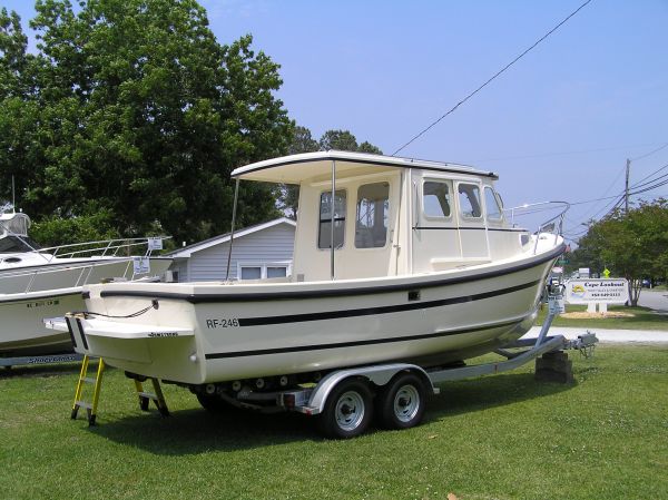
Note the waterline stain on the aft hull. As per plans the waterline should be almost parallel to the chine. My concern was two fold. First, that the V-berth would end up with the foot end higher than the head end. I had a friend with a boat with this problem and they were forced to sleep with their head squeezed in the bow. The other thought was this posistion would be inefficient when running at displacement speeds (not a big deal if the plan is to run at planing speeds). I spent hours doing weight & balance calculations and they indicated moving as much weight forward as possible would be a benefit. I did so including the tanks & batteries.
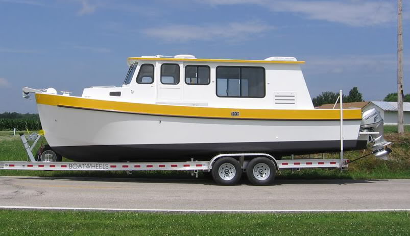
The black bottom paint in the photo above is level with the waterline.
As it ended up I still am a little heavy aft (about 2 " at the transom) and although the berth is fine I do feel it does hurt performance a little. I will say to date I have not had the 80 gallon water and fuel tanks anywhere near even 1/2 full. If they were I think it would indeed bring the bow down some and help the situation.
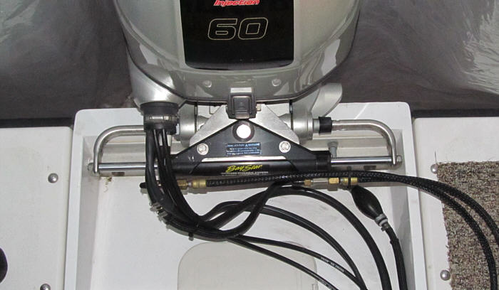
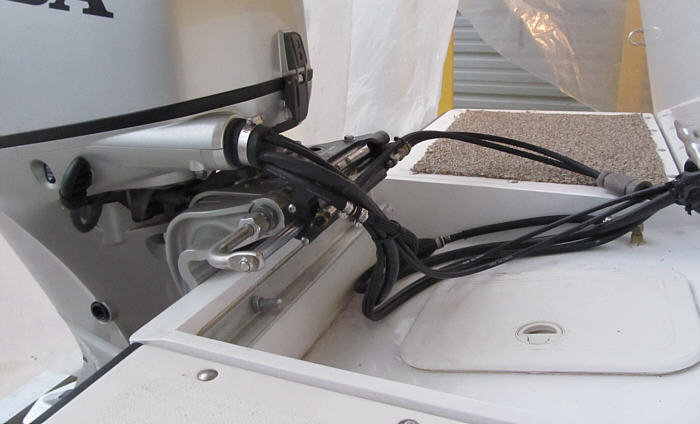
Here are a few photos of the bracket with the outboard installed. There are probably more than needed but I thought they might be helpful to someone working through a similar situation.
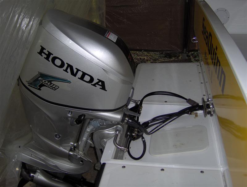
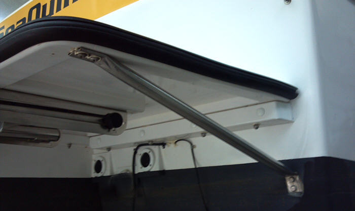
In the trimmed down posistion
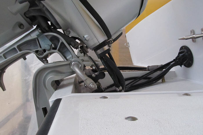
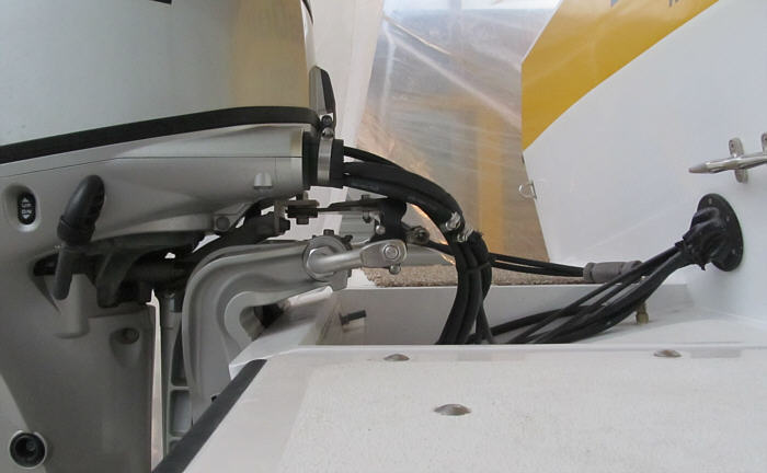
In the trimmed up posistion - note if splashwell was narrower the linkage would hit the swimplatform.
Also, the O/B is mounted about an inch higher than the mounting pad top. If it were lower there would
be a clearance problem without a wide well OR narrower platforms.
Here are a few photos of how Rosborough handles the situation and they served as a guide when building my bracket. In hindsight I wish I had made my box narrower, like theirs. I was thinking it needed to be wide enough to include the steering linkage but by having the mounting plate extend above the box's sides the steering linkage would have cleared. Also, since I was planning on operating in full displacement mode I wanted my bracket bottom to become a hull extension and provide additional lift. I assume since the Rosborough is mainly a planing hull it wasn't as important.
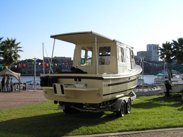

Overall a very clean installation.
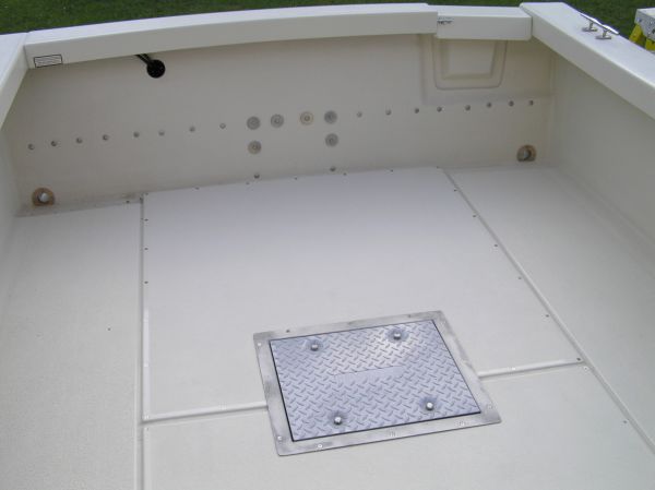
In this view of the interior transom the bolts holding the bracket and platfirms are evident .
Here is a link to a company that makes a similar bolt on unit -
Stainless Marine Outboard Bracket